CoringSpec Editorial
Quick Answer: Using a concrete core drill stand requires securing the base with an anchor bolt or vacuum plate, adjusting column plumb with corner leveling bolts, tightening carriage slide gibs to eliminate play, and advancing the bit smoothly using the feed handle without jerky force.
Stand Components & Mechanical Anatomy
A precision core drill rig consists of four primary mechanical assemblies:
- Baseplate: Heavy cast aluminum or steel base with anchoring slot, vacuum chamber, and 4 threaded corner leveling bolts.
- Precision Column (Mast): Extruded aluminum or steel profile featuring a machined rack-and-pinion gear track and angle tilt adjustment (0° to 45°).
- Motor Carriage: Sliding carriage equipped with adjustable brass slide guides (gibs) or roller bearings that house the core drill motor.
- Feed Handle & Gearbox: Dual-ratio or single-ratio feed wheel that translates manual rotation into controlled, high-leverage carriage downforce.
Step-by-Step Operating Workflow with a Stand
- Anchor and Level the Mast: Secure the base using a 1/2″ mechanical drop-in anchor. Level the mast using a torpedo level and lock the 4 corner leveling screws against the slab.
- Mount Motor to Carriage: Slide the motor collar into the carriage clamp or bolt the quick-disconnect mounting plate (e.g., standard 4-bolt or dovetail bracket). Torque clamping bolts securely.
- Adjust Carriage Slide Tension (Gibs): Engage the feed handle and check carriage movement. The carriage should glide smoothly down the column without sticking, but must have zero side-to-side rocking play (<0.5 mm). Adjust brass gib screws to remove slop.
- Install Bit & Connect Water: Thread on the diamond core bit using water-resistant grease on the spindle threads (per Husqvarna bit-changing instructions). Connect the water supply and adjust flow to maintain continuous water delivery at the cutting face.
- Initiate Drilling: Start the motor at full rated speed in air. Slowly rotate the feed handle to lower the diamond segments gently into the concrete. Do not slam the segments into the aggregate.
- Maintain Controlled Feed Rate: Apply continuous, smooth rotational force to the feed handle. Monitor the motor amperage / LED indicator to maintain maximum cutting efficiency without bogging down the gearbox.
Angle Drilling Setup (0° to 45° Penetrations)
For drainage pipes, seismic anchors, or angled utility conduits, loosen the angle tilt locking bolts on the mast support strut. Adjust the column scale to the desired angle (e.g., 30° or 45°) and re-torque locking bolts to the stand manufacturer recommended locking torque. When angle drilling, always use mechanical drop-in anchors (vacuum bases cannot support angled shear loads).
Operational Checklist Table
| Stage | Check Item | Standard / Target | Adjustment Method |
|---|---|---|---|
| Pre-Drill | Carriage Slide Gibs | Smooth travel, zero lateral play | Tighten lateral set screws |
| Setup | Base Leveling Feet | All 4 feet firmly bearing on slab | Adjust 17 mm corner bolts |
| Drilling | Feed Handle Leverage | Smooth, continuous rotation | Switch feed handle to fine-feed ratio if equipped |
| Post-Drill | Carriage Travel Lock | Locked at top of column when parked | Engage carriage brake knob |
Related Guides & Tool Links
- Anchor installation procedures: How to Anchor a Core Drill Stand
- Explore verified drill stands: Core Drill Stands Hub
- Handheld vs stand comparison: Handheld vs Stand Core Drilling
- Calculate bit RPM: Core Drill RPM Calculator
Sources
Stand operating standards sourced from CSDA Stand Operation Guide, Hilti DD-ST Rigs Manual, Husqvarna DS 500 Documentation, and Milwaukee Tool Diamond Coring Technical Reference.
Carriage Maintenance, Lubrication & Gib Adjustment
To maintain glass-smooth carriage advancement and prevent binding on high-feed commercial rigs:
- Cleaning Slide Ways: Wipe down the machined column faces daily with a clean rag. Never apply heavy grease to the exposed column rack, as wet concrete slurry will stick to grease and form an abrasive lapping compound that grinds away brass gibs.
- Dry Lubricant Spray: Spray the aluminum column slide surfaces with dry PTFE or silicone lubricant spray.
- Adjusting Brass Gib Screws: Tighten the 4 lateral carriage set screws until snug, then back off 1/8 turn. The carriage should descend smoothly under moderate feed wheel pressure with zero rocking play.
Rack-and-Pinion Backlash & Column Rigidity Tolerances
Precision hole drilling requires exact tolerances along the vertical mast. Machined steel rack-and-pinion tracks convert feed handle torque into downforce. Over time, concrete slurry entering the gear track can cause backlash (play between the pinion gear and rack teeth).
To adjust gear backlash on commercial core rigs, loosen the eccentric pinion bushing locking bolt, rotate the eccentric collar until gear teeth mesh with zero slop (<0.2 mm backlash), and re-tighten. This ensures buttery smooth carriage travel and prevents the carriage from creeping down the column under the dead weight of the motor.
Products for this page

Core drill
VEVOR Z1Z-9260
11.8" max · corded
Largest VEVOR budget stand tier for holes approaching 12".

Core drill
Husqvarna DM 540i
4" max · cordless
Lightweight cordless commercial handheld / light stand work.

Core drill
VEVOR Z1Z-CF02-80
4" max · corded
Budget handheld wet coring for 3.1", 4" plumbing/HVAC holes when a stand rig is not required.
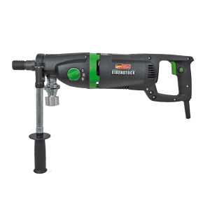
Core drill
CS Unitec ETN 162/3 P
6.375" max · corded
Professional wet or dry drilling handheld or stand diamond coring
Paid links. Specs on this site come from manufacturer documentation, not from the retailer.