CoringSpec Editorial
Quick Answer: To secure a core drill stand with a mechanical anchor, drill a 1/2″ or 5/8″ hole using a rotary hammer, set an internal-thread drop-in anchor with a setting tool, thread in a high-tensile anchor rod through the stand’s center slot, tighten the heavy clamping nut, and adjust the 4 corner leveling screws until the column is rigid and perfectly plumb.
Why Stand Rigidity Is Critical to Bit Performance
A diamond core bit requires perfect coaxial alignment. If the stand flexes or rocks even 1-2 millimeters during drilling, the spinning core barrel tilts inside the kerf. This causes severe side-wall binding, rapid segment loss on one side, extreme motor vibration, and increases the risk of jamming or snapping anchor bolts.
Required Anchoring Hardware & Tools
- Rotary Hammer: SDS-Plus rotary hammer with matching 1/2″ or 5/8″ carbide bit.
- Drop-In Concrete Anchors: Zinc-plated or stainless steel female drop-in anchor (e.g., 1/2″-13 or 5/8″-11 thread).
- Anchor Setting Punch: Matching manufacturer setting tool to expand the internal plug fully.
- High-Tensile Threaded Rod & Nut: Grade B7 all-thread rod with heavy-duty spherical washer and hex nut.
- Level & Box Wrench: 3/4″ or 15/16″ combination wrench and a 9″ magnetic torpedo level.
Step-by-Step Anchor Installation Workflow
- Locate & Mark the Anchor Hole: Position the drill stand over the target penetration mark. Align the bit centerline with the target, then mark the anchor slot position on the concrete (typically 8″, 12″ behind the bit center).
- Drill the Anchor Pilot: Drill perpendicular into the concrete to the exact depth specified by the anchor manufacturer (typically 2″ for 1/2″ drop-ins). Blow out all concrete dust from the hole with compressed air or a hand pump.
- Set the Drop-In Anchor: Insert the drop-in anchor flush or slightly below the concrete surface. Insert the setting punch into the anchor and strike firmly with a 2 lb hammer until the punch shoulder contacts the anchor lip, expanding the internal anchor cone.
- Thread In the Anchor Rod: Thread the Grade B7 rod fully into the anchor (minimum 6 full thread turns).
- Position Stand Base & Torque Clamping Nut: Slide the drill stand slot over the threaded rod. Place the heavy domed washer and nut onto the rod, then hand-tighten.
- Level and Plumb the Column: Adjust the 4 leveling screws on the stand base corners using a wrench until the column bubble level is centered in both X and Y axes.
- Final Clamping Torque: Torque the main center clamping nut to approximately 45-55 ft-lbs. Re-check the 4 corner leveling screws to ensure all four contact the slab firmly with zero rocking play.
Rig Stability Verification Matrix
| Inspection Point | Verification Method | Acceptance Criteria | Action if Failed |
|---|---|---|---|
| Column Plumb | Torpedo level on machined column face | Bubble centered in 90° cross-planes | Adjust corner leveling bolts |
| Base Rocking Play | Push firmly on top of column by hand | Zero deflection / zero base lift | Retorque center nut; tighten leveling feet |
| Carriage Gib Play | Grasp motor carriage and check side-to-side play | Smooth travel with <0.5 mm lateral play | Adjust brass slide-way gib screws |
| Anchor Engagement | Inspect rod thread protrusion | Nut fully engaged with 2+ threads showing | Use longer threaded rod if shallow |
Related Guides & Tool Links
- Compare stand vs vacuum setups: Vacuum Base vs Anchor Guide
- Explore verified stands: Core Drill Stands Hub
- Operational stand checks: How to Use a Core Drill Stand
- Calculate bit speed: Core Drill RPM Calculator
Sources
Anchoring engineering based on ACI 355.2 Qualification of Post-Installed Mechanical Anchors, CSDA Drill Rig Anchoring Standards, Hilti Drop-In Anchor Technical Data, and Red Head Fastener Specifications.
Through-Bolting & Ceiling Anchoring Procedures
When drilling horizontally through vertical walls or inverted through ceilings, drop-in expansion anchors may be subject to tension pullout or shear loads. Through-bolting provides the ultimate structural security:
- Through-Bolt Wall Setup: Drill a 5/8″ hole completely through the concrete wall. Pass a Grade B7 all-thread rod through the wall, placing a 6″ x 6″ x 1/2″ steel backing plate on the opposite wall face before torquing the stand nut.
- Ceiling / Inverted Rigging: When anchoring overhead, use heavy-duty wedge anchors or undercut mechanical anchors rated for cracked concrete in tension (per ACI 355.2). Always install a secondary steel safety chain tethering the drill stand to an independent ceiling beam.
Products for this page
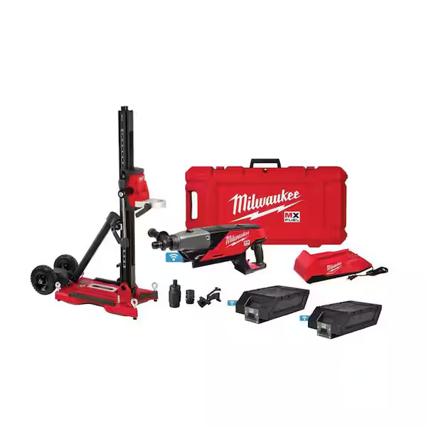
Core drill
Milwaukee MXF301-2CP
6" max · cordless
Premium cordless wet or dry drilling reinforced-concrete coring up to 6" with stand capability.

Core drill
Husqvarna DM 406 H
25.6" max · hydraulic
Heavy-duty hydraulic stand coring approaching 24, 25.6" in reinforced concrete.

Core drill
Hilti DD 150-U
6.375" max · corded
Premium versatile handheld or stand mounted use benchmark up to 6-3/8".

Paid links. Specs on this site come from manufacturer documentation, not from the retailer.